Learning how to machine complex geometries using CNC requires more than selecting a complicated toolpath. It demands practical planning, accurate modeling, and disciplined machine control. Freeform surfaces, deep cavities, thin walls, and angled features can challenge even experienced machinists. A small programming error may leave visible ridges across an otherwise precise part. That happens.
This guide examines the decisions behind reliable CNC machining for complex components. It considers CAD and CAM preparation, workholding, cutting-tool selection, spindle speed, feed rate, and multi-axis movement. Each choice affects surface quality, machining time, tool life, and dimensional accuracy. A five-axis machine may reach difficult surfaces efficiently, but it still needs careful collision checks and stable fixturing. Three-axis equipment can also produce excellent results when the design is divided into sensible setups.
Real workshop experience shows that simulation cannot replace inspection. Material may vibrate differently than expected. A tool may deflect inside a narrow pocket. Heat can gradually change the finished dimension. These details deserve measurement with probes, gauges, or a coordinate measuring machine. Good results come from controlled adjustments, not confident guesses.
The discussion also addresses common mistakes, including excessive stepovers, weak workholding, poor stock allowance, and neglected tool runout. Some recommendations may require revision for specific materials or machines. That uncertainty is important. Reliable CNC practice combines proven engineering principles with honest testing, documented settings, and continuous reflection. The goal is not merely to cut a complex shape, but to produce it safely, repeatedly, and within the required tolerance.
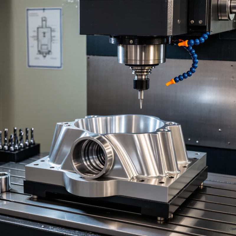
Complex geometries in CNC machining include deep cavities, angled walls, undercuts, sculpted surfaces, and blended edges. These shapes demand more than a simple drilling or pocketing strategy. A machinist must understand how the model, cutting tool, fixture, and machine axes interact. It is not magic.
For example, a turbine-like surface may require continuous tool movement across several angles. A short, rigid cutter can reduce vibration inside a narrow cavity. Smaller stepovers usually improve surface quality, but they also increase machining time.
In practice, I verify the toolpath before cutting metal. Simulation can reveal collisions, gouges, and unreachable areas. Still, simulation is not perfect. Fixturing errors, tool deflection, and heat can change the final result. Measuring a test feature often exposes assumptions that looked correct on screen.
Tips: Keep the model clean and define realistic tolerances. Use larger tools where access allows. Leave controlled material for finishing passes. Check thin walls with probing or careful inspection. Record failed approaches, too; they often improve the next setup.
Complex parts also benefit from staged machining. Roughing removes material efficiently, while semi-finishing creates a consistent surface for the final pass. For deep features, changing the setup may be safer than forcing one tool to reach everything. A small orientation change can prevent chatter and protect a fragile edge. I would rather question an elegant toolpath than trust it blindly.
Complex geometries begin with the right machine, not the most expensive one. A five-axis CNC machine reduces repositioning, but it still needs adequate travel, spindle torque, and rotary-axis accuracy. ISO 230-1 provides methods for evaluating machine-tool geometric accuracy. Use those tests before trusting a tight-tolerance quotation. Deloitte’s 2024 Smart Manufacturing and Operations Survey found that 86% of manufacturers expect smart manufacturing to become a major competitiveness factor. That makes probing, simulation, and process data practical requirements, not decorative features.
Tool selection should follow the material, corner radius, and cutting engagement. For hardened steel, shorter carbide tools and controlled stepovers reduce deflection. For aluminum, polished flutes and strong chip evacuation prevent built-up edge. I have found that tool length is often chosen for access, then regretted during finishing. A 3+2 setup may be more stable than continuous five-axis motion when the geometry allows it. Workholding deserves equal attention. Use a low-profile fixture, support thin walls, and leave machining stock near clamping points. Vacuum holding can work for broad plates, but it becomes unreliable around interrupted surfaces.
Tips: Verify tool reach with a full digital simulation. Measure the fixture after loading. Leave a sacrificial skin on fragile features. The International Organization for Standardization recommends periodic accuracy checks, yet many shops inspect only after a failure. That is a costly habit. Record probe offsets, tool wear, and fixture repeatability after each trial. Some assumptions will be wrong. Let the first part expose them safely.
Machine-axis selection and workholding planning for common geometric requirements
Planar pockets can normally be produced on a 3-axis machine with one primary setup. Indexed multi-face parts generally require a fourth rotary axis or multiple orientations, while complex undercuts and continuous freeform surfaces typically benefit from simultaneous 5-axis motion. Use short, rigid tools and secure the workpiece with a fixture that exposes the cutting area while minimizing deflection.
Preparing CAD Models and CAM Toolpaths for Complex Parts
Complex CNC parts begin with disciplined CAD preparation, not aggressive cutting. Remove duplicate surfaces, repair gaps, and define clear datums before importing the model into CAM software. A watertight solid helps prevent false collisions and incomplete toolpaths. NIST’s GCR 04-867 study estimated that poor interoperability costs the capital facilities industry about $15.8 billion annually. That finding still matters. Broken model data can create expensive rework long before the machine starts.
Tips: Keep the stock model visible. Mark critical tolerances. Simulate holder clearance, not only cutter movement. Use smaller tools only where geometry demands them. A perfect simulation can still hide a weak setup.
For five-axis or sculptured surfaces, divide the part into logical machining zones. Select tools according to reach, rigidity, and corner access. Then control stepovers, lead angles, and linking moves separately. A large stepover may shorten cycle time, but it can leave visible scallops on curved walls. The International Federation of Robotics reported 553,052 industrial robots installed worldwide in 2022, showing how rapidly automated production is expanding. Yet automation does not replace judgment. A first toolpath often needs revision after inspecting real chips, vibration, and surface marks. Do not trust default feeds blindly. Record actual cutting behavior, then update the CAM process for the next part.
Executing multi-axis machining operations step by step requires planning before cutting metal. Begin with the part’s datum structure, material, and critical tolerances. A five-axis setup can reduce repositioning, but it cannot correct poor fixturing. Secure the workpiece, verify tool clearance, and simulate every rotary movement. Watch the holder, not only the cutter. That detail matters.
Generate roughing paths with controlled engagement and consistent chip load. Leave a small, measurable allowance for finishing. Then inspect the remaining stock before changing tools. For curved surfaces, adjust tool orientation gradually instead of forcing sharp angular changes. This reduces marks and avoids sudden load spikes. According to the 2024 Deloitte Smart Manufacturing survey, 86% of manufacturers expect smart manufacturing to become a major competitiveness driver within five years. That expectation depends on reliable process data, not attractive software screens.
Finish critical surfaces using shorter stepovers, stable spindle speeds, and clean coolant delivery. Measure datums after roughing, especially when heat has built up in the workpiece. The NIST Engineering Statistics Handbook emphasizes traceable measurement and uncertainty evaluation for dependable manufacturing decisions. In practice, a 0.01 mm reading is not automatically trustworthy. Probe calibration, fixture movement, and temperature can change its meaning. I have seen perfect simulations fail because the fixture blocked a rotary axis. Recheck reality. Multi-axis machining rewards disciplined verification, yet some toolpaths still need human judgment when cutting conditions behave differently than predicted.
Complex CNC parts rarely fail because of one dramatic mistake. More often, small errors accumulate around deep pockets, thin walls, and blended surfaces. Inspect critical datums before finishing. A probe can verify part location, while a coordinate measuring machine checks form, position, and profile.
The 2023 ISO Survey recorded 1,265,216 ISO 9001 certificates worldwide, showing how widely documented quality systems support repeatable production. Still, certification cannot replace careful measurement on the shop floor.
Surface finishing should match both function and inspection results. A roughness check may reveal tool wear that visual inspection misses. On curved surfaces, inspect several points across the toolpath, not only the center. Watch the edges. Excessive polishing can remove material and alter a tolerance. ISO 21920 defines modern profile-based methods for evaluating surface texture, but operators still need stable sampling conditions and calibrated instruments.
Geometry optimization begins with evidence. Compare measured deviation maps against cutting direction, tool reach, and fixture stiffness. A 0.02 mm error near a mounting face may matter more than a larger deviation on a nonfunctional wall.
I have seen “perfect” finishing hide a poor datum strategy. That deserves reflection. Adjust stepovers, feeds, support, or tool orientation only after identifying the error pattern. Record each change, then remeasure the same features under the same conditions. That discipline turns inspection data into a reliable machining process.
They include deep cavities, angled walls, undercuts, sculpted surfaces, and blended edges. Simple drilling is not enough.
Simulation can reveal collisions, gouges, and unreachable areas before cutting metal. It is useful, but never perfect.
Use short, rigid cutters when access allows. Smaller stepovers can improve the surface, but machining takes longer.
It can reduce repositioning and protect delicate features. A simpler angled setup may sometimes be more stable.
Match the tool to the material, corner radius, and cutting engagement. Excessive tool length often causes deflection during finishing.
Use low-profile fixtures, extra support, and controlled stock near clamping points. A sacrificial skin can protect fragile walls.
Probing can verify part location. Coordinate measuring equipment can check form, position, and profile.
Small errors can accumulate around pockets, thin walls, and curved surfaces. Tool wear, heat, fixture movement, and poor datums may contribute.
Compare measured deviations with cutting direction, tool reach, and fixture stiffness. Change one process detail, then measure the same feature again.
Record them. A failed toolpath can expose weak assumptions and improve the next setup. A perfect screen result may still disappoint.
Machining complex geometries with CNC requires careful planning, accurate programming, and consistent process control. To understand how to machine complex geometries using CNC, begin by analyzing the part’s curves, deep cavities, thin walls, undercuts, and tight tolerances. Select a suitable CNC machine with the required number of axes, then match cutting tools, workholding methods, speeds, and feeds to the material and design. A clean CAD model is essential, while CAM software helps generate collision-free toolpaths, define appropriate stepovers, and control tool engagement throughout the operation.
The machining process should be performed step by step, typically beginning with roughing to remove excess material, followed by semi-finishing and finishing passes for precision surfaces. Multi-axis movements can improve access to difficult features and reduce repositioning errors. After machining, inspect the part using suitable measurement methods, remove burrs, and apply any required surface finishing. Reviewing inspection results and machining performance can further optimize toolpaths, reduce cycle time, improve surface quality, and ensure reliable production of future complex components.

Robotic CNC